Geospatial data for geotechnical data
Geotechnical data is inherently geospatial, yet it’s often trapped in formats that don’t take advantage of this spatial nature.
Understanding what geospatial data is, and why geotechnical data fits this model, unlocks powerful workflows for analysis, visualization, and integration.
What is geospatial data?
Section titled “What is geospatial data?”Geospatial data is information that is associated with a specific location on Earth. There are two main types:
Raster data
Section titled “Raster data”Continuous surfaces represented as grids of pixels, like satellite imagery or digital elevation models (DEMs). Think of these as spatial “heat maps” showing how values change across a landscape.
Vector data
Section titled “Vector data”Discrete objects represented by geometric shapes with attached properties. According to the Open Geospatial Consortium (OGC) Simple Feature Access specification, vector data uses three basic geometries:
- POINT: A single location (like a borehole collar)
- LINESTRING: A connected series of points (like a borehole path or geological layer boundary)
- POLYGON: An enclosed area (like a site boundary or geological unit)
Unlike many CAD drawings, which often lack georeferencing, geospatial data explicitly encodes real-world coordinates through defined spatial reference systems.
Why geotechnical data is naturally geospatial
Section titled “Why geotechnical data is naturally geospatial”Ground investigation data is collected at specific locations on Earth’s surface and extends into the subsurface. Every piece of geotechnical data has inherent spatial characteristics:
- Borehole locations: Specific easting, northing, and elevation coordinates
- In-situ tests: Performed at discrete depths below known surface locations
- Laboratory samples: Extracted from specific depths at known locations
- Monitoring data: Time-series measurements at fixed spatial positions
This makes geotechnical data naturally suited to 3D geospatial vector representation:
| Geotechnical Element | Geospatial Geometry | Example |
|---|---|---|
| Borehole/CPT location | 3D LINESTRING Z | From surface to final depth |
| Sample point | 3D POINT Z | Sample at 5.2m depth |
| Geological layer | 3D LINESTRING Z | Clay layer from 2.1m to 4.7m |
| In-situ test | 3D POINT Z | SPT at 3.0m depth |
The spatial awareness advantage
Section titled “The spatial awareness advantage”When geotechnical data is treated as geospatial data, it becomes spatially aware, it ‘knows’ the relationships between locations, distances, and coordinate systems. This enables:
- Automatic coordinate transformations
- No more manual coordinate conversion errors when working with different engineering drawings or survey systems.
- Spatial queries and analysis
- Spatial queries allow you to query things like:
- "Show me all boreholes within 50m of the proposed foundation"
- "Find SPT values in sandy soils between 5-10m depth"
- Integration with other spatial datasets
- Geotechnical data can be directly combined with:
-
- Topographic maps and aerial imagery
- Existing infrastructure and utilities
- Environmental data (flooding, contamination)
- Planning and regulatory boundaries
Spatial Reference Systems
Section titled “Spatial Reference Systems”Geospatial data achieves its spatial awareness through Spatial Reference Systems (SRS), standardized definitions that link coordinates to real locations on Earth.
See the Spatial Reference Systems explanation for more.
Breaking free from format silos
Section titled “Breaking free from format silos”Traditional geotechnical data formats (AGS, DIGGS, GEF) are good at data exchange but create data silos that limit interoperability. The purpose of Bedrock is NOT to become THE standard for GI data, because we don’t need 15 instead of 14 competing standards. By recognizing geotechnical data as geospatial data, we can:
- Visualize data in any GIS software (QGIS, ArcGIS)
- Analyze using spatial statistics and geostatistical methods
- Integrate with BIM models, CAD drawings, and web applications
- Share through standard web mapping services
- Process using the rich ecosystem of geospatial analysis tools. We like Python, but with open formats you can use any language or toolset, like R or Julia.
Geospatial databases
Section titled “Geospatial databases”Geospatial databases are specialized databases that can store and work with geospatial data. Unlike regular databases that only handle text and numbers, these databases understand spatial relationships. By storing geospatial data in databases rather than files, you gain powerful querying capabilities and can efficiently manage large, complex 3D spatial datasets.
Geospatial databases like PostGIS (PostgreSQL-based) or GeoPackage (SQLite-based) combine the benefits of:
- Relational structure: Store hierarchical geotechnical data efficiently.
- Spatial capabilities: Perform geographic queries and analysis
- Multi-user access: Server databases like PostGIS support concurrent users; GeoPackage is better for single-user or read-heavy scenarios
- Data integrity: Enforce relationships and constraints
- Performance: Spatial indexing makes queries fast even with large datasets
The foundation for modern workflows
Section titled “The foundation for modern workflows”Treating geotechnical data as geospatial data isn’t just about changing file formats, it’s about unlocking modern, integrated workflows that connect subsurface investigations with the broader built environment. This spatial foundation enables many possibilities from viewing subsurface data on a web map to integrating digital twins of infrastructure projects.
Bridging GIS and Engineering Workflows
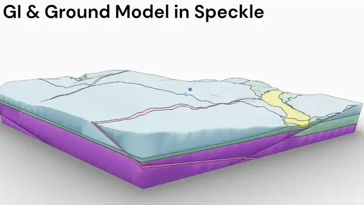
Section titled “Bridging GIS and Engineering Workflows”Most engineering tools, like Revit and BIM 360, aren’t natively geospatial and often rely on local coordinate systems. Even Civil 3D, which supports projected coordinate systems, can be difficult to align cleanly with GIS data.
Bedrock avoids fragile format conversions by structuring geotechnical data in open geospatial formats like GeoPackage, and using platforms like Speckle to integrate with AEC tools. This enables boreholes, tests, and ground models to be visualized directly alongside CAD and BIM models in Revit, Civil 3D, or Rhino.